And cite for them the parable of two men. To one of them We gave two gardens of vine, and We surrounded them with palms-trees, and We placed between them crops. Both gardens produced their harvest in full, and suffered no loss. And We made a river flow through them. - Quran, 18. The Cave (al-Kahf) (32-33)
There are two types of gates. The miller regulates the level of the brook with the spillway gates or by-pass sluices, and uses the control gate or inlet sluice to control the water flow and operate the mill.
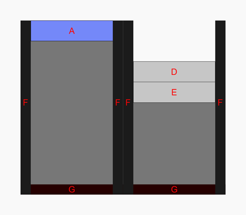
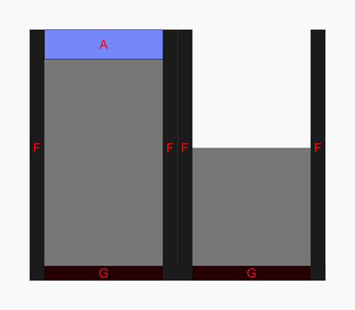
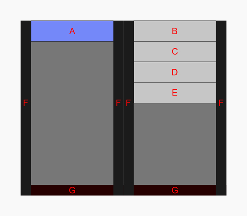
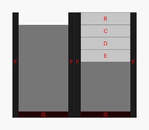
The spillway gates are placed in the dam and are used to regulate the flow rate of the brook when the mill is not functioning.
When calculating the height and dimensions of the spillway gates, one needs to take into account the maximum flow rate that the brook could attain. If the dimensions were insufficient, in case of a severe flood the water could overflow the entire dam, which would make it impossible to halt the mill.
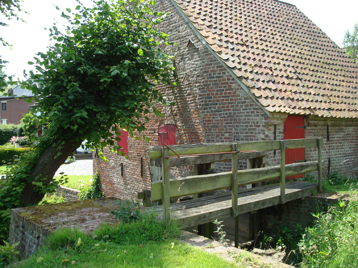
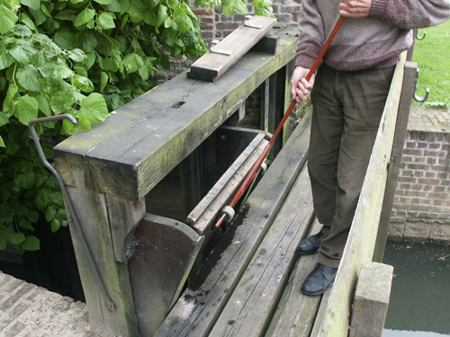
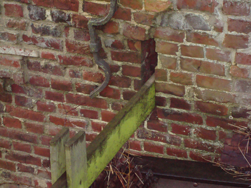
The spillway gates are accessible from a wooden footbridge that spans the brook at the back of the mill. To operate the gates, the miller uses a hook, a tool consisting of a metal rod, with a smaller transversal rod at its end in the shape of a T. This tool grips the two metal hooks of the spillway gate, so that it can be lifted or put back in its place.
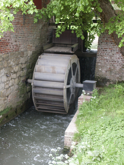
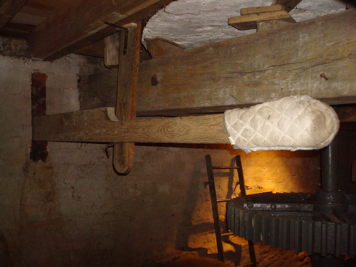
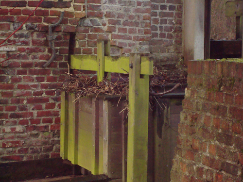
The control gate is used to regulate the flow rate of water necessary to operate the wheel. This gate is situated approximately in the middle of the head race. It will be opened when the water level is sufficient to make the wheel turn. The control gate allows the miller to regulate the speed and hence the torque of the water wheel.
The control gate is operated from within the mill by means of a lever. The lever system has an additional advantage: when the control gate is closed, a downward pressure can be applied, which assures a better locking of the head race.
Some mills also have a debris grille (also called mill grate) in front of the control gate: this is a sieve with relatively small mesh opening, used to intercept smaller branches carried by the brook. This particular mill is not equipped with a debris grille and we haven't found sufficient evidence to confirm its existence in the past.
The next chapter at a glance:
Where you will learn how the natural energy of water, a combination between gravity and mass, is used to drive the overshot water wheel and how the curved and inclined blades increase the overall output.