And it is He who made the night a covering for you, and sleep for rest; and He made the day a revival. And it is He who sends the winds, bringing advance news of His mercy, and We send down from the sky pure water. To revive dead lands thereby, and to provide drink for the multitude of animals and humans We created. - Quran, 25. The Criterion (al-Furqan) (47-49)
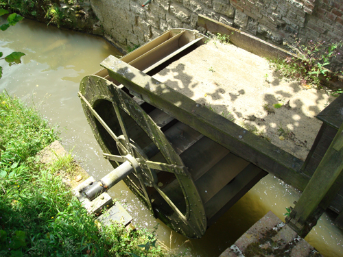
The water wheel of Pede's Mill has a diameter of 2.20 metres and a width of 1.10 metres. Its diameter is somewhat smaller than the height of the dam: the lower part of the wheel must be situated just above the water level of the brook downstream. The space between the wheel and the brook is called clearance. This is very important as the wheel turns in the opposite direction of the flow downstream. The wheel must be situated just above the water level in order not to be slowed down. This also means that a high water level, for instance after heavy rainfall, will make it much more difficult to operate the mill, as the level of the tail race will be too high and the water wheel will not turn freely.
The shaft rests on a support wall that is part of the abutment sidewall and turns in a roller-bearing. The wheel shaft enters the building of the mill and communicates with the internal transmission system of the workshop.
The water wheel is provided with blades. Here, the special shape of the blades, curved and inclined relative to the axis of the wheel, gives a better performance, as it allows the miller to use almost all the water's force. This type of water wheel is called bucket wheel. The wheel is constructed around the wheel shaft: the central flange of the wheel is fixed to the wheel shaft and supports the radial spokes. These in turn carry the rim, which constitutes the upper part of the water wheel. The base of the water wheel is mounted on the rim by means of angle irons. The buckets are constructed between the rim and the base.
Just before the dam, a wooden floor is supported by beams in the brook's bed: the sill or apron. Downstream we find the runway, this is the base plate above which the water wheel turns. The runway of overshot water mills (with feeding at the upper part) is placed considerably lower than the sill.
The base of the dam is a horizontal beam in the river bed. This beam supports the vertical sluice posts, which are separated by approximately 1 metre. The gates are introduced between these sluice posts and can thus be lifted or lowered as required. A horizontal cross beam on top of the sluice posts finishes the framework. The complete construction of beams which forms the dam is called the ark.
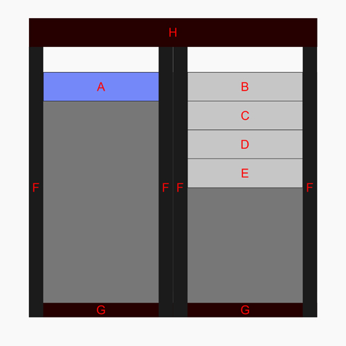
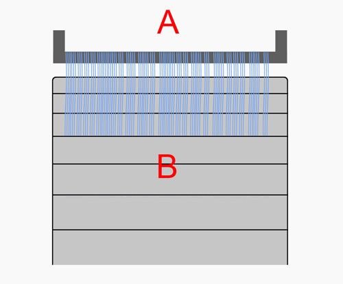
The head race transports the water over the wheel and slightly beyond the centre of the wheel shaft. When water flows into the buckets, the part of the wheel on the far side of the dam weighs more than the empty part on the near side of the dam. This weight difference makes the wheel lose its balance and turn due to gravitational force. The buckets empty themselves of water when their position is inverted by the rotation of the wheel.
An overshot water wheel is driven by the differential of the watercourse. It takes its energy more from the weight of the water than from the increase of the brook's water speed. The natural energy of water is the result of a combination between gravity and mass. These two factors, gravity (differential) and mass (flow rate), will determine the available power. The bucket wheel takes kinetic energy from water and transforms it into usable power (= energy per time unit).
The success of this transformation determines the output of the water wheel. It depends on a number of variables like the wheel type, water supply, resistance of the roller-bearing, transmission etc. An overshot water wheel with a relatively simple construction already achieves a respectable output of 50 to 60%. By using curved and inclined blades (buckets), the output can be raised to about 85%. The specific shape of the buckets retains the water as long as possible and the use of thinner sheet iron increases their capacity.
When calculating the opening of the control gate, it is important to avoid spouting water over the buckets. A correct calculation will prevent the loss of water and consequently a loss of motor torque.
The construction, dimensions and inclination of the head race are also of paramount importance. The head race is slightly narrower than the water wheel, by a distance of approximately 10 centimetres on either side. This allows the water to stabilise itself very quickly inside the buckets and allows the air inside an empty bucket to escape, which achieves a maximum output. This also helps to reach a gradual transfer of the water pressure on the wheel.
This type of bucket wheel is mainly used on brooks with a reduced flow rate and has the advantage of self-regulation. When the resisting torque increases, the wheel slows down and the buckets are filled to a greater extent. A more efficient filling of the buckets increases the motor torque of the wheel. The speed will reach a stabilisation point when a balance is attained between the motor torque and the resisting torque. The wheel needs to be carefully balanced in order to provide maximum power.
The water wheel is the soul of the mill and its most representative element.
The next chapter at a glance:
Where we give a more detailed description of the different gears used to transmit the rotary movement to the workshop inside the mill.